Toy Train Layout Wiring - Crossing Relay
| Basic | Intermediate | Advanced | Wire Management | Bus Wiring | 120V Train Room |
| Glossary | Wire Sizes | Switches | Load Calculations | Soldering | Troubleshooting |
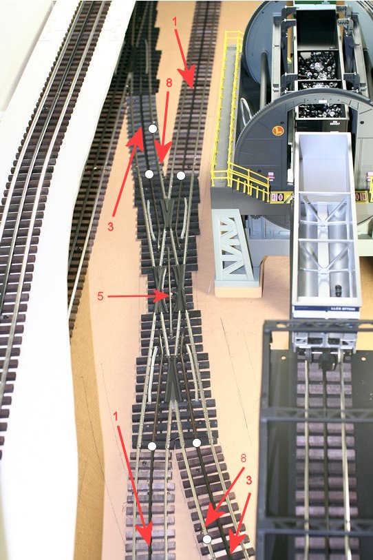
Crossing with Relay for Track Power Control
(located at South end of
Run Room)
This Ross Eleven Degree Crossing has Two
Tracks Powered with Two Separate Inputs.
The relay switches the crossing center to the Black Main while the
relay coil is energized.
 |
East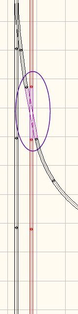 West |
Electronics Under Table
The bridge rectifier is from surplus. There are 2 tubing
standoffs behind the circuit board screws.
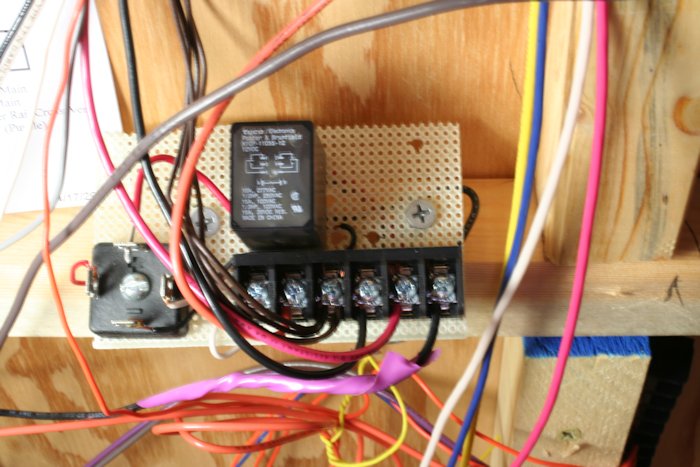 |
Circuit Card Posted with Circuit Board 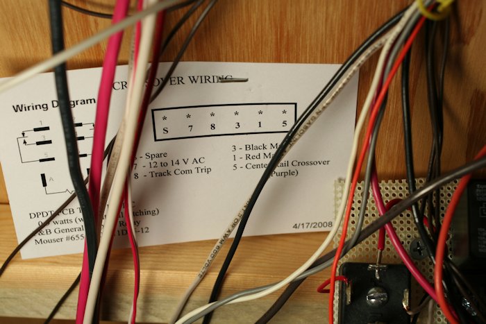 |
Run Room Wire Color Coding
Black and Red #12 for outside Main Tracks
Variable Voltage, White for all Commons,
Red #16 for Z-Stuff Switch Machines
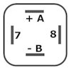 AC power (7 and 8 contacts) is converted to DC current for the A and B relay coil. DC activated relays are more common and usually cheaper. |
 This
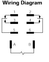
DPDT relay can be replaced with a SPDT This
DPDT relay can be replaced with a SPDTrelay. The 2, 4, and 6 terminals are not used. The relay action is visible with the clear cover. Relay Description DPDT PCB TERM 12VDC 0.9 watts (without coil latching) P&B General Purpose Relay Mouser #655-K10P-11D55-12 |
| Terminal Wires | Function | Switch Center Rail in Center of Crossing |
|
7 RED 8 BROWN 3 BLACK 1 RED 5 PURPLE |
13 VAC White Common Blk Main Track Red Main Track Middle Center Rail |
Red 13 VAC terminal for Z-Stuff
Switch Machines Switched Track Common - Train wheels activate Powered by Black Main Center Rail Voltage Powered by Red Main Center Rail Voltage Rail has Black Main Power when Coil AB is energized |
| Question? Contact the SSPRR COO (Chief Operating Officer) using the email button to the right. (If email link is absent, please enable JavaScript.) |
|