Phasing Transformers
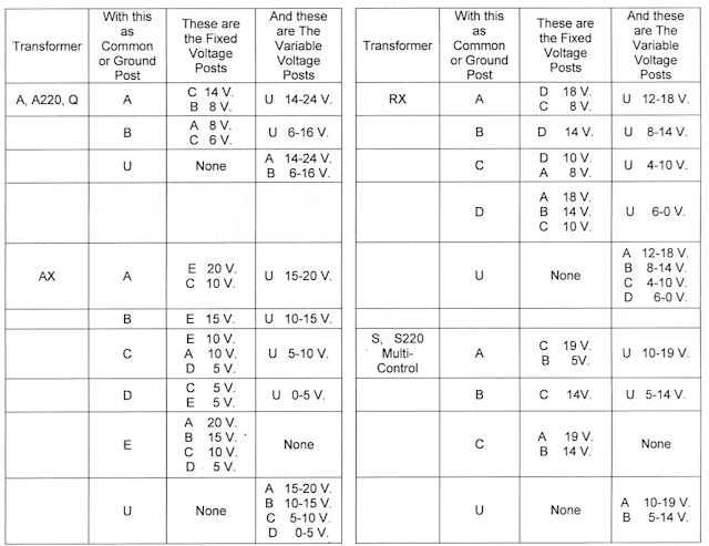
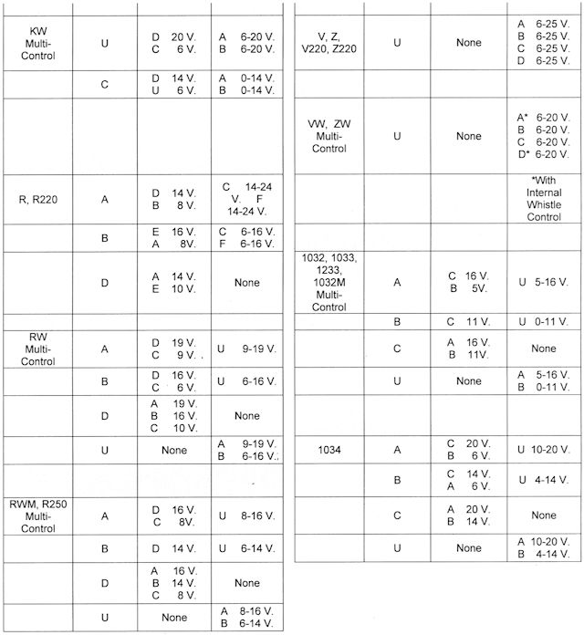
With a toy train layout, if you have two transformers powering two different divisions and they're "out of phase" it would be possible to inadvertently run 40 volts through a locomotive when it's over the center rail insulating track pin separating the divisions. This condition is unsafe. This procedure shows how to phase two or more transformers. (Some transformers have power taps that do Not use the common. If you use a power tap that doesn't use the transformer common keep that wiring separate from all other wiring. See examples in the chart at the end of Phasing.)
Transformer "bricks" that are designed to feed controllers must also be phased. They do not all arrive with the same phasing.
Preparation and Hook-Up
- Decide on a Master transformer. All other transformers will be phased to the Master.
- For phasing, start with the Master transformer and the first to be phased. Transformers should not be connected to any track or accessories. In the photo below, the MTH Z4000 on the right will be used as the Master and the postwar ZW on the left will be phased to the Z4000.
- Connect all commons on the transformers to be phased to one bus bar (terminal strip with all screws common). Plug 110 V power cords into 3 pronged plug strip with on/off switch.
(See Diagram)
- Set one variable voltage post (handle) on each of the two transformers at 14V. (When phasing a fixed voltage transformer use the fixed voltage, such as 18V, on both transformers.)
- Turn switch on to power 110V plug strip.
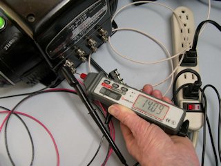
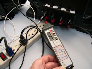
- On each transformer, use an ac voltage meter to check the output between the chosen variable voltage post and the common to be sure the output is the stated voltage. The voltages don't have to be a perfect match. See meter readings with both transformers set at 14V.
 |
 |
Phasing Modern Transformers or Combination Postwar and Modern
- For modern transformers containing electronics, use a voltmeter or 14V lamp for phasing.
- Measure between the Master transformer variable voltage post and variable voltage post on second transformer. Or place a 14V lamp between the two posts.
- There should be no more that one or two volts showing on the voltmeter. Or the lamp won't light.
The meter reads 28V which indicates the
transformers are "out of phase".
A 14V volt lamp would burn bright
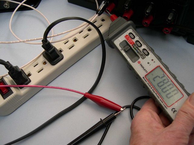
When transformers are "out of phase" turn the power plug around on the transformer being phased.
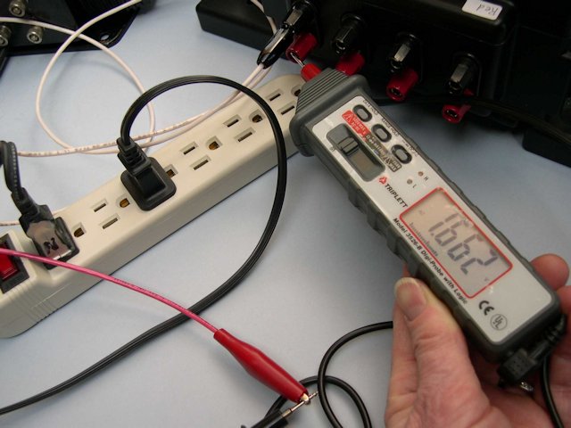
ZW plug was turned around and voltage reads 1.66V indicating transformers are in phase. Mark the side of the plug that goes into the wide or neutral socket when transformer is in phase.
Phasing Postwar Transformers Only
If you are phasing only postwar transformers (those without electronics such as a postwar ZW) you can do so with the spark test as follows:
- Set up transformers as described above.
- Connect a long wire (if needed) to the variable voltage post you will use for comparison to the Master transformer.
- Touch the long wire from Master transformer to the variable voltage post on the second transformer. There should be no sparks. If you get sparks, turn the power plug over in the power socket and check again.
All Modern Transformers must be Checked for Correct Phasing
Manufacturers of modern transformers with polarized plugs intend for all their transformers to be in phase and most are in phase. Some have been wired backwards so all have to be phased before using with other transformers. Since the plugs are polarized they can't be turned around. Replacement polarized plugs are available at home improvement and hardware stores.
POSTWAR LIONEL TRANSORMER CIRCUITS WITH COMMON GROUND
The voltages specified are the nominal or 'no load' voltages and will drop somewhat under operating conditions, depending on the load and the rated wattage of the transformer.
