Toy Train Layout Wiring - Load Calculations
| Basic | Intermediate | Advanced | Wire Management | Bus Wiring | 120V Train Room |
| Glossary Plus | Wire Sizes | Switches | Load Calculations | Soldering | Troubleshooting |
The following formulas, examples, and charts can be used to "guesstimate" loads on a toy train layout. Circuit protection and wire sizing are determined by the total amps. Transformer sizes and total transformers needed are determined by total watts. When measuring current/amps always measure under load (with train or accessory running). Size circuit protection as small as possible for normal operation.
Limit Transformer loads to 75% of the continuous load.
Example - A 400 VA (watts) transformer will handle a 300 watt
continuous load.
Experience has shown:
A small modern steam engine with DC motor and circuit board that
converts AC to DC for motor will pull about 1 A and over 2 A with
the smoke unit on. Overload the engine by pulling 20-30 cars on a
main line with 8 to 10 A circuit protection and the motor or circuit
board will fry before the circuit protection trips. Lesson - Size
circuit protection for Divisions according to the loads used by
trains. For smaller consists, 3 or 4 Amp circuit is good.
ABA six motored passenger engines and 10 lighted passenger cars can
pull 8+ A. A lighted passenger car can pull 0.8 amps. For long
passenger trains cars can be converted to LED lighting to minimize
load.
A modern Big Boy can pull a 50 car freight train up a grade at as
little as 4.5 A.
Electrician's Formulas
|
Description |
Formula |
Abbreviations |
||
|
Ohm's Law for Amps |
I = V/R |
V = Line Voltage |
||
|
volts = A x Resistance |
V= IR |
Vd =Voltage Drop |
||
|
resistance = V ÷ amps |
R = V/I |
R = Resistance |
||
|
Calculate Voltage Drop |
Vd = 2KIL/CM |
I = Current |
||
|
Calculate Loads |
VI = Watts |
CM = Circular Mil |
||
|
L = Distance |
||||
|
K = 12 for Copper |
||||
|
K = 18 for Aluminum |
||||
|
MCM = 1,000 CM |
||||
|
AWG = American wire gauge |
||||
|
CM VALUES |
||||
|
AWG |
CM |
|||
|
10 |
10,380 |
|||
|
12 |
6,530 |
|||
|
14 |
4,107 |
|||
|
16 |
2,583 |
|||
|
18 |
1,624 |
|||
|
20 |
1,022 |
|||
|
22 |
642 |
|||
| LOAD CHART | WIRE AMP RATINGS |
|
Lionel Postwar Items |
Estimated Watts |
|
AC Motor
for Engines |
15 |
|
AC Motor
for Big Steam |
25 |
|
AC Motor -
Big for Access. |
25 |
|
022 Sw and
Controller lamp |
5 |
|
Lamp |
2.5 |
|
Metered while running |
|
|
2046
Hudson w/Tender |
45 |
|
623
Switcher |
27 |
|
Modern Era |
|
|
DC Motor
for most Engines |
15 |
|
DC Motor
for Big Steam |
20 |
|
Smoke Unit |
25 |
|
Lamp |
2 |
|
Headlight
- big |
5 |
|
Marker
Light |
2 |
| Metered | |
| MTH Pass Car w 2 lamps |
5 |
|
MTH
Caboose w 1 lamp |
7 |
|
Size |
Wire Types |
Amp Rating |
|
24 |
CAT-2
3 pair Telephone |
2.1 per
conductor |
|
24 |
CAT-5
4 twisted pair Data |
2.1 per
conductor |
|
22 |
7
conductor irrigation cable |
5 per
conductor |
|
20 |
2
conductor thermostat wire |
7.5 per
conductor |
|
18 |
thhn for
AC electrical |
10 |
|
16 |
2
conductor lamp cord |
13 per
conductor |
|
16 |
thhn for
AC electrical |
13 |
|
14 |
thhn for
AC electrical |
15 |
|
12 |
thhn for
AC electrical |
20 |
|
10 |
thhn for
AC electrical |
25 |
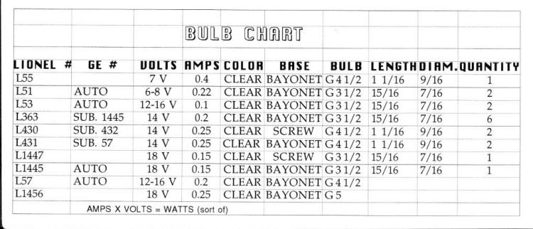
This Laminated Chart of Lionel Postwar Bulbs was a Gift from a TCA Club Member

Parallel and Series Wiring Examples
 |
Residential
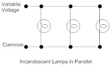
Wiring is Parallel wiring. For train layout buildings
and lighting, Parallel wiring is normally used. The
voltage remains the same the length of the circuit. Parallel Circuits Formula It = I1 + I2 + I3 (I = current/amps) Total current equals sum of amps through each resistor/lamp. |
Some 4 Lamp Yard Lights are Wired with 2 Lamps in Series

Series Circuits Formulas
Vt = V1 + V2 + V3
Total voltage equals sum of voltages across each
resistor/lamp.
Rt = R1 + R2 + R3
Total resistance equals the sum of the individual
resistors.
Light Bulbs
-
MTH Trains modern bulbs here Light Bulb Guide Sheet
| Question? Contact the SSPRR COO (Chief Operating Officer) using the email button to the right. (If email link is absent, please enable JavaScript.) |
|
