Toy Train Layout Wiring - Bus Wiring
| Basic | Intermediate | Advanced | Wire Management | Bus Wiring | 120V Train Room |
| Glossary | Wire Sizes | Switches | Load Calculations | Soldering | Troubleshooting |
Bus Wiring Defined
Bus, wire, bar, or strap used to distribute power that is tapped at intervals.
Introduction
Bus wiring is my personal preference for wiring toy train layouts. All toy train "players" need to decide on the wiring methods that make sense to them. The foolproof way to wire a layout is to wire a section, test run trains, and start on the next area (even it you have to run temporary home runs for test power). Any faults will turn up while you're in the area and you won't have to go back later.
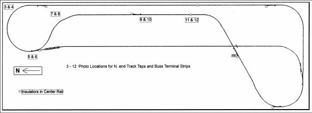
Black Main
All track in the Run Room can be accessed from here. The Black
Main includes three Divisions, North, South, and Yard. Photos
below diagram show some of the bus wiring for the North Division.
 |
 |
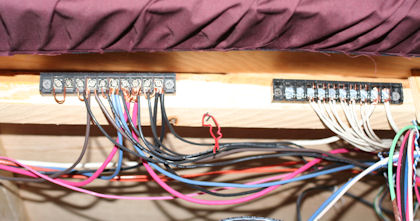
| Photo 3 The bottom/outside track is Black. |
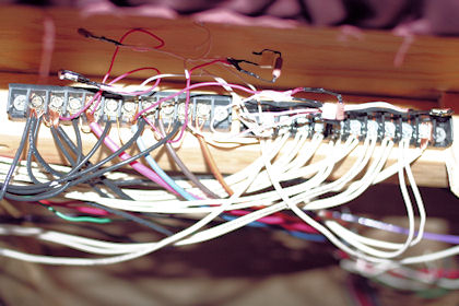
Photo 4 NE Bus for Black, Red, Blue, Brown, and Orange tracks. Gizmos tied between hots and commons are DCS Filters. Taps used on all track are #16 solid with black for center rail and white for outside rails. |
 |
 |
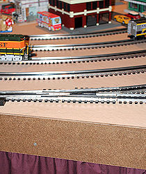
| Photo 5 Black track has turnout to Yard. |
Photo 6 NW Bus for Black, Red, Blue, Brown, and Orange tracks. The DCS Filters are among first filters tried in Run Room. |
 |
 |
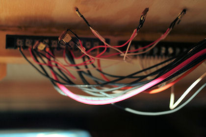
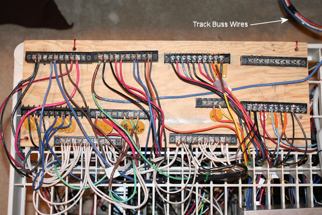
| Photo 7 Home run wire wyes here. |
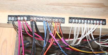
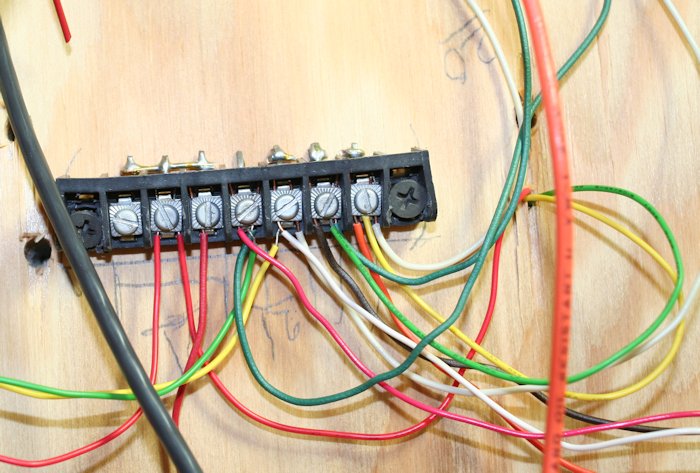
Photo 8 Each color wire has 3 to 5 terminals common on back of strip. The purple tape indicates switched track (for stub tracks). All the white wire (common) terminals are tied together on the back of the terminal strip. (see example) |
 |
 |
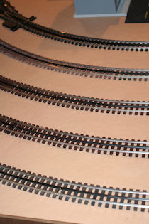
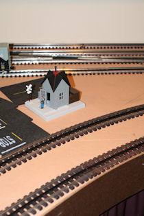
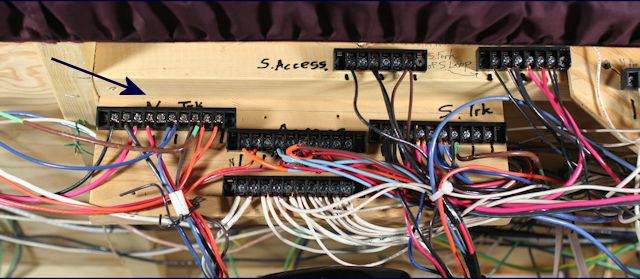
| Photo 9 Tracks from bottom to top are blk, red, brn, blu, red, and blk. |
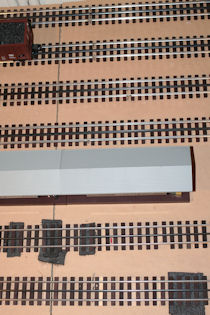
Photo 10 The big wires are in and out home run wires. The smaller black and white wires are track taps. |
Arrow shows Home for the North Black Main
Control Cart where Black Main is tied into Controls and Power
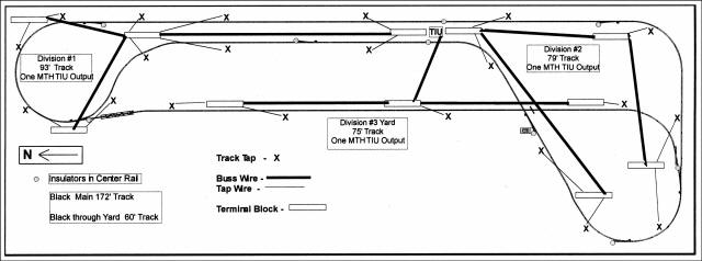
Wiring Diagram for Three Divisions of
Black Main
(all taps are not shown)
Wire taps to track are made so that every third track is tapped or
every track joins a tapped track, which would be after every third
joint. ( -- -- -- tap->-- -- -- tap>-- )
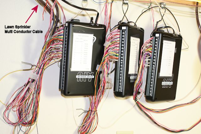
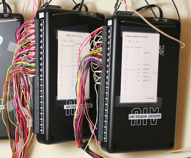
MTH DCS AIUs used as Terminal Strips for Turnout Controls
Considering the cost of terminal strips for wiring from the Z-Stuff switch machines to the controllers on the Run Room control panels, the AIUs for current and future remote control are ideal terminal strips. Just run the two switch machine control wires in and out of the AIU terminals (from switch machines to control panels). One controller can control paired switch machines so paired turnouts only need two wires per pair.
Run Room Requires 3 AIUs for 28
Controllers
The 3 AIUs can control the Ross Switches on the Main, Ceiling and
Stub Tracks, and Helix control panels.
The Industrial Area is
not wired for wireless remote control.
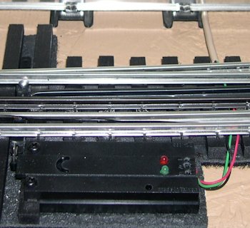
| The Z-Stuff Switch Machine for the Ross Switch is wired with surplus 4-wire 22 gauge telephone wire. This Switch Machine has the earlier screw terminals. |
 |
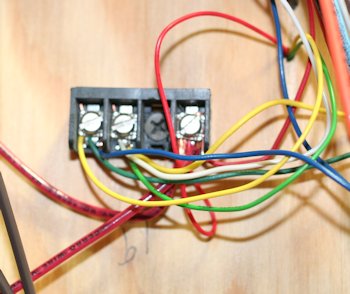 |
This terminal strip is mounted under the table and controls two Ross Switches with one Z-Stuff controller or AIU tap. See the table hole at upper right with pre-wired Z-Stuff switch machine wires. The red wires are the 14V power from an AC transformer. The yellow and green wires at trip wires. The blue and white wires are trip wires from the controller. |
Under Table Terminal Strip for Two Controllers
The cards on the AIUs show the AIU tap numbers tied to the numbered controllers and the pair wire colors. Most of the controllers switch a pair of turnouts.
| Question? Contact the SSPRR COO (Chief Operating Officer) using the email button to the right. (If email link is absent, please enable JavaScript.) |
|