3 Rail O Gauge Toy Trains
Runner and Guest Access Bridges - Atlas
Atlas 3-Rail Pratt Truss Bridge with Lift Assist - Construction Photos and Drawings
Return to Atlas 3-Rail Pratt Truss Bridge with Lift Assist
Design and Construction
The Run Room CEO (Chief Engineering Officer) very generously
designed and constructed the modification to an Atlas O 3-Rail Deck
Girder Bridge for easy access by runners and visitors. The
two bridges were installed before track was laid in 2006. In
June 2012 the CEO made working drawings of his preliminary
drawings. The fabrication photos were taken in 2006.
Locate the hinge point vertically at about the top of the rails,
then the gap between the rails can be almost zero, if the rails are
cut square. Horizontal location of the hinge point is not very
important and your choice. The tolerances for the fabrication
are very generous.
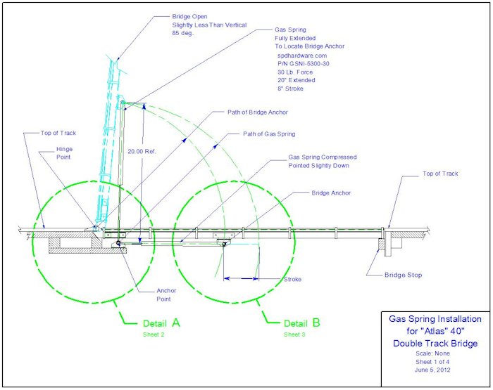
The bridge is designed so the gas spring sends it down just past the
down stop so there will be good pressure for electrical contact.
Location of the gas spring end fittings influences the bridge action. A line drawn
between the end fittings should point as close as possible to the
hinge point to maximize down force when closed, but if you get
carried away with this it will take two hands and a foot to get the
bridge off of the 85 degree vertical position. This design has about
a two inch offset when the bridge is down. A little playing around
can make it work. The weight of a bridge is a big factor.
Completed Double Track Bridge
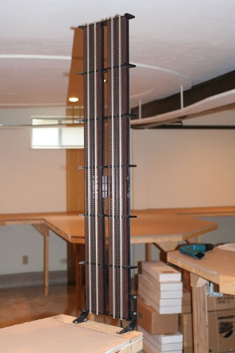
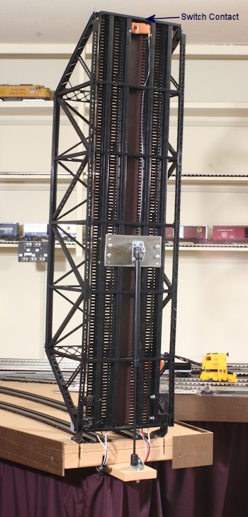
| The Atlas double track bridge during construction before the super structure is attached. To close or open the bridge, grab the deck | The finished bridge in up position with gas spring holding the bridge up. The bridge track and switch contact are powered with the stranded wires from the table. |
 |
 |
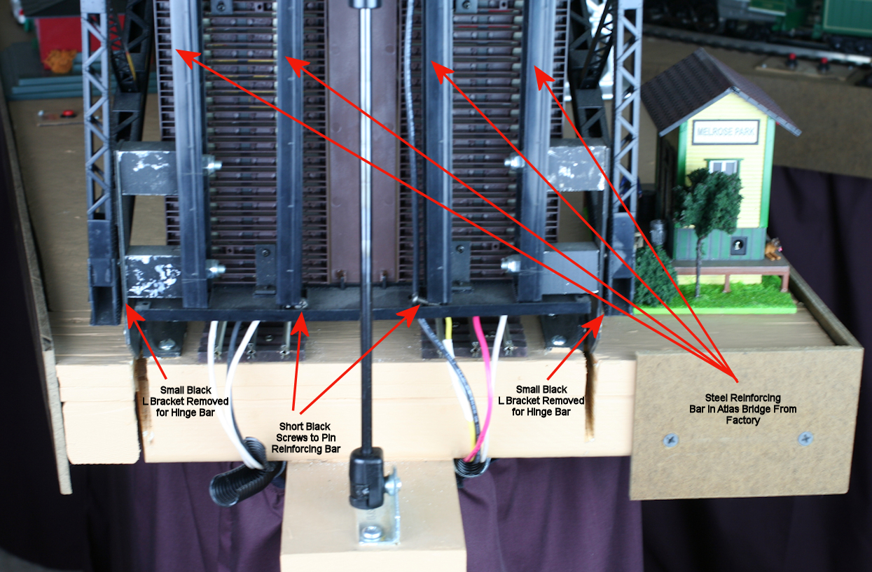
The 2 small black L brackets attached with tiny phillips screws were
removed to allow space for the hinge plate.
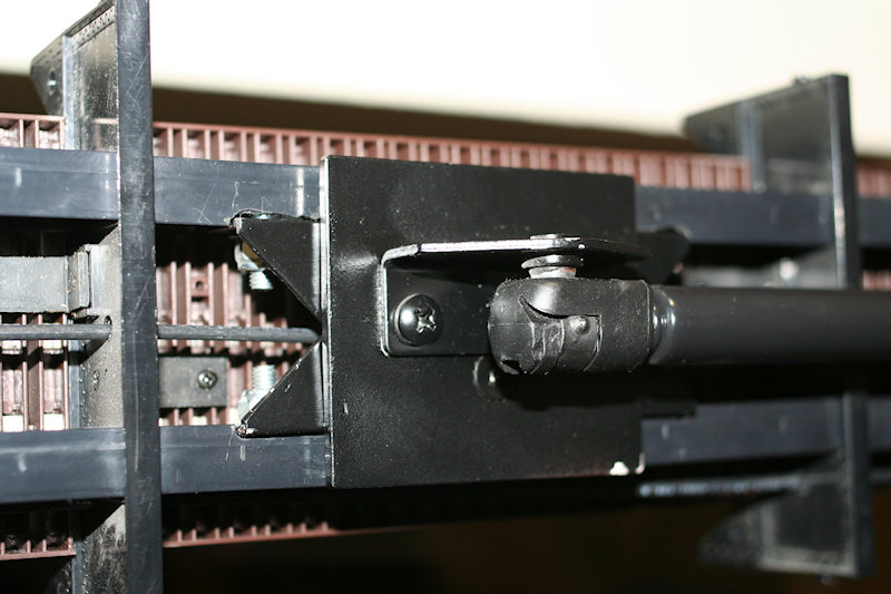
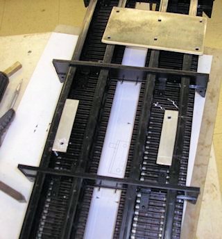
The 4 steel reinforcing bars that Atlas installed in the bridge make
this installation possible. See the drawing below (Detail A -
Hinge and Gas Spring Hardware Fabrication and Installation) that
refers to the bars (end view on right). The reinforcing bars are
loose in a channel of each long plastic girder. Photo below
with details added 2021. Note the two black screws that
prevent the middle reinforcing bars slipping down.
Completed Single Track Bridge
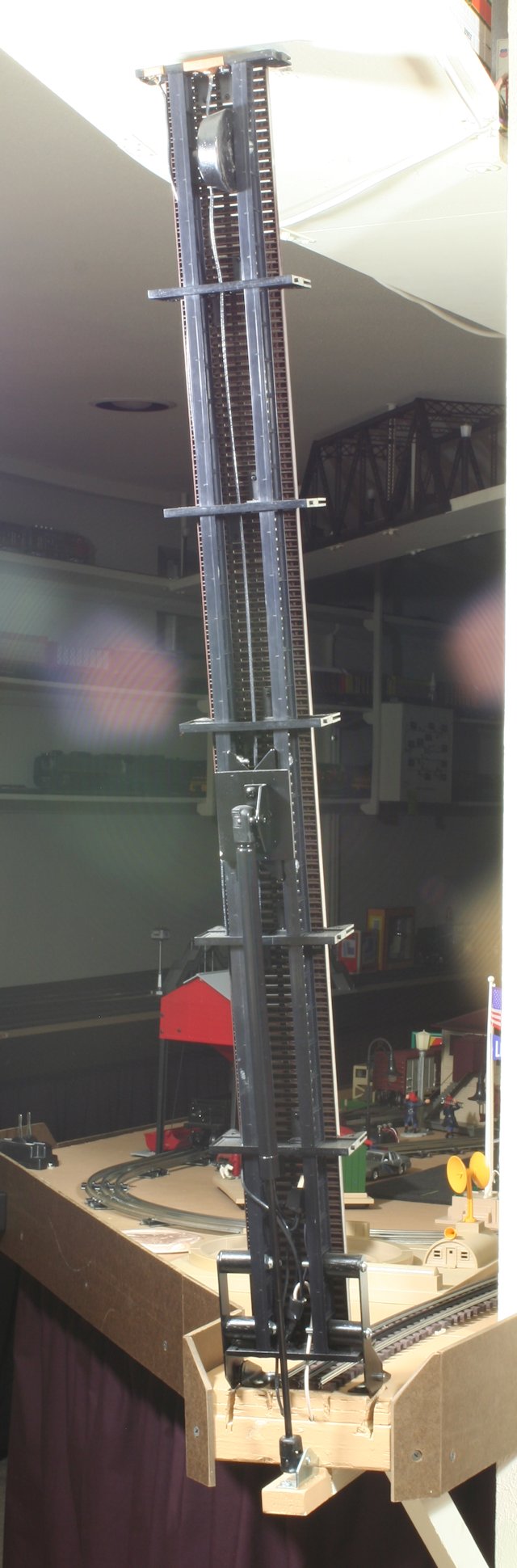
| The single track bridge
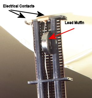
construction used the Double Track Drawings as a guide. Note the "lead muffin" at the end of the single track bridge to hold the bridge against the electrical contacts. "Playing around" with the gas spring parameters might negate the need for a "lead muffin" but the muffin was handy and works great. It was time to run trains! The "lead muffin" weighs about 1 pound 4 ounces. The CEO said you may be able to get rid of that weight by adding a 1/8" to 1/4" spacer to the mounting bracket at the top of the lift spring. See detail close up photos below for gas spring attachment revisions for the single track width. Note that the angle iron was cut to make a V for accessing the nuts. The spring is slightly compressed in the UP position. |
 |
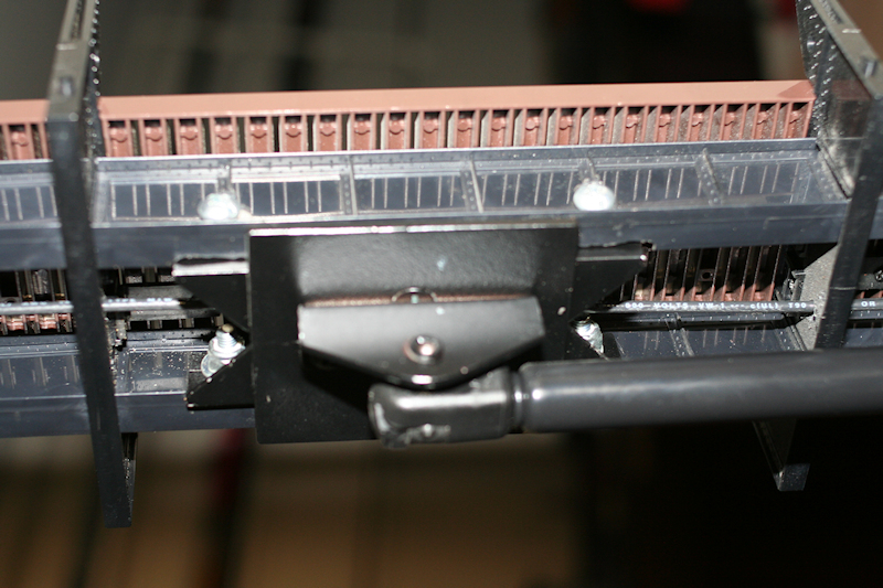
| Close up of "lead muffin" at the end of the single track bridge. The Electrical Contacts power the bridge track and trigger the Engine Safety Relay. |
 |
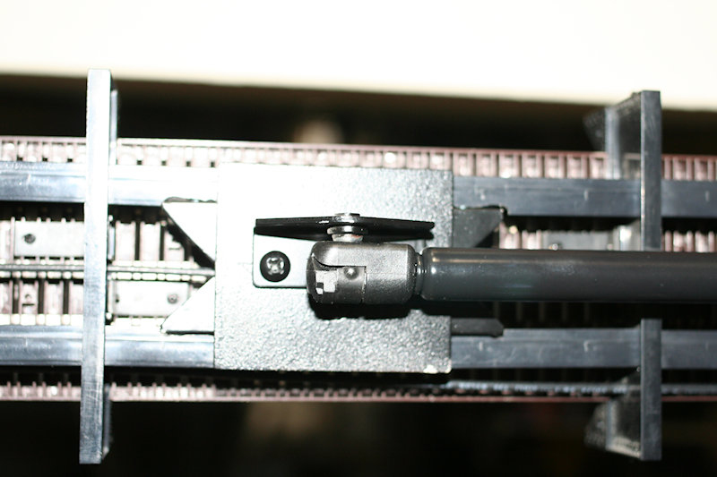
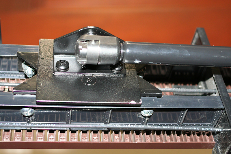
Top gas spring attachment revised for the single track width.
Note the angle iron was cut to make a V
for accessing the nuts.
 |
 |
 |
 |
Atlas 3-Rail Pratt Truss Bridges with Lift Assist Drawings and Parts
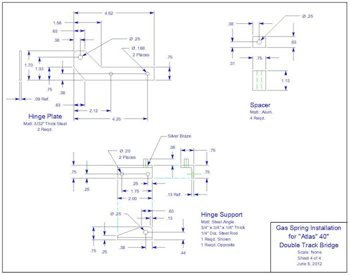
Hinge and Gas Spring Hardware Fabrication and Installation also in PDF
Detail A - Hinge and Gas Spring Hardware Fabrication and Installation also in PDF
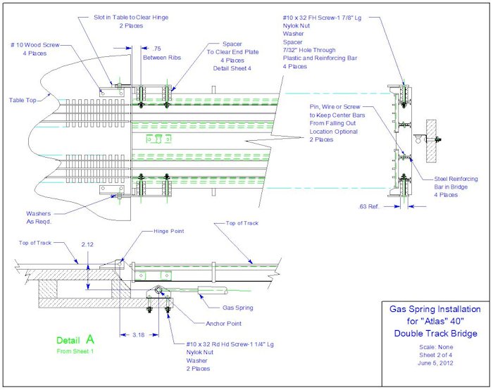
Single Track Bridge Variables - On the Run Room installation the horizontal distance between the Hinge Point and Anchor Point is 1.68" Not 3.18" butting the table gas spring bracket against the table. The up position of the single track bridge is closer to 80 degrees. If it goes to 85 degrees, the bridge hits the Ceiling Track structure.
Hinges
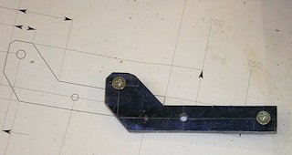 |
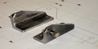 |
Hinge Parts Detail also in PDF
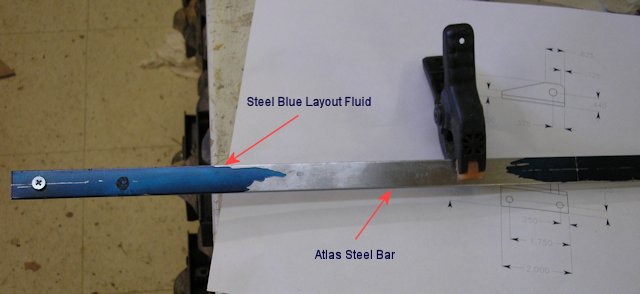
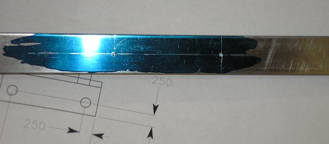
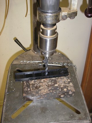
Atlas Steel Bar Strips in Girder Slots
All new bridge hardware is attached to these bars. Girder hinge hole positions are determined by holding the bridge up to the table mounted hinges with temporary track on table and matching the bridge and table track heights. (probably, 2006 was a while back) Temporarily secure bar in place. Start drill bit through the plastic girder to mark the steel bar so both outside bars can be removed and drilled at the same time. You may be able to drill all four angle bracket holes at once. If not, drill hinge holes first, mount bridge to hinges and air spring to table then mark the air spring bracket location for the aluminum plate. Remove hinges from bridge and slip steel bars out to drill for gas spring plate mounting brackets.
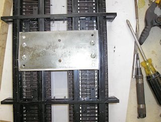
Bridge Girders
| → The girder end plate at hinge end is drilled for a wiring chase. Gas spring mounting plate is installed between outside girders. (below right) ↓ Gas spring mounting plate and angle brackets. |
 |
 |
 |
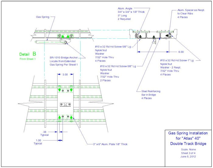
Detail B - Gas Spring Hardware Fabrication and Installation also in PDF
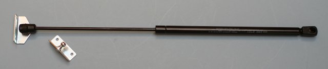
Gas Springs
Two Track Bridge Part #GSNI-5300-30 Single Track Bridge
Part #GSNI-5300-20
The mounting bracket (4) is Part# BR-1010.
at Associated Spring Raymond
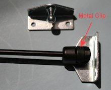
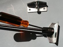
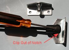
Attach or Remove the Gas Spring
Insert the blade of a screwdriver under the metal clip at about a 45
degree angle, and gently pry up to dislodge the clip until you can
pull the clip away from the slot. Do not fully remove the
clip. Repeat this step with the other end.
 |
 |
 |
Materials List for Atlas O Track Pratt Truss Bridges with Lift
Assist
(Purchase, fabricate, or use shop surplus using the above plans and
information.)
|
Atlas O 3-Rail Double Track
Pratt Truss Bridge Kit or Atlas O 3-Rail Single Track Pratt Truss Bridge Kit (these kits include the 4 or 2 Steel Reinforcing Bars in the Girder Slots) Gas Spring parts from Associated Spring Raymond: Double Track Bridge Gas Spring #GSNI-5300-30 or Single Track Bridge Gas Spring #GSNI-5300-20 Two Mounting Brackets per Spring # BR-1010 For Fabrication: Hinges 2 3/4" x 3/4" x 1/8" thick x 2" long Steel Angle 1 1/4" diam. x 1+" long Steel Rod for Hinge Pins 4 5/8" x 3/4" x 1 1/8" long Aluminum Spacers for Double Track Bridge OR 4 3/4" Hardwood Dowel Spacers for Single Track Bridge 2 3/32" x 1 3/4" x 4 5/8" Steel for Hinge Plates Hinge Mounting Hardware 4 #10 Wood Screws Washers as required 4 #10 x 32 FH Screws-1 7/8" long 4 Nylok nuts 4 Washers 4 Spacers |
Gas Spring Plate and Plate Mounts to Girders 1/8" x 3" x 6" Aluminum Plate for Double Track Bridge 1/8" x 2 3/8" x 2 3/4" Aluminum Plate for Single Track Bridge 2 1/8" x 3/4" x 3/4" x 3" long Aluminum Angle (drill holes to fit Girder ribs) 4 Square Aluminum Spacers as Required to Clear Ribs in Girders Plate Mounting Hardware 4 #10 x 32 Rd Hd Screw-5/8" Long 4 Nylok Nut 4 Washer Plate Angle Mounting Hardware 4 #10 x 32 Rd Hd Screw-1" long 4 Nylok Nut 8 Washer - 2 Required BR-1010 Mounting Hardware 2 #10 x 32 Rd Hd Screw-5/8" Long 2 Nylok Nut 2 Washer Mounting Gas Spring Bracket to Layout 2 #10 x 32 Rd Hd Screw-1 1/4" long 2 Nylok nuts 2 Washers |