Slide Conversion Control Box
 Why
a Control Box?
Why
a Control Box?
To make the system automated, the control box provides a bridge
between the computer, the carousel project, and the camera. For each
slide, the control box triggers the carousel to move one step
forward, then focus the camera, then take the picture. The process
repeats until the carousel is fully converted.
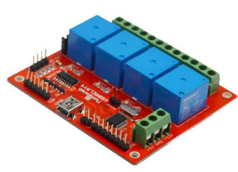
The green USB Relay Module has been updated by Numato to the red
Module shown below.
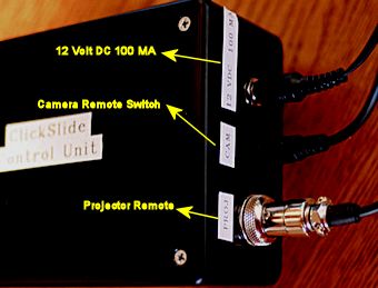
Control Box Materials:
- Box from Radio Shack - 2 1/4" x 4" x 6"
- Numato 4 Channel USB Relay Module
- 4 each - 6/32 flathead machine screws, 4 nuts, and 4 standoffs
- 2.5mm jack for camera cable - Radio Shack #274-245 (mounts in box)
- 4-pin cable jack - Radio Shack # 274-002 (mounts in box)
- 4-pin female plug - Radio Shack #274-001 (The 4-pin jack and plug replace the remote-control-end of the carousel's remote control cable. The carousel-end of the remote control (5-pin) is left unchanged.)
- 12V DC 100mA power supply
- 12V DC jack to match your power supply (mounts in box)
- 9' 2.5mm camera cable for shutter trigger listed with Camera Setup (connects between box and camera)
- USB A to Mini B for box to Computer connection
| Numato 4 Channel USB Relay Module - 2013 Upgrade | The USB port is on the opposite end. |
 |
 |
Control Box Construction
(click here for printable diagrams)
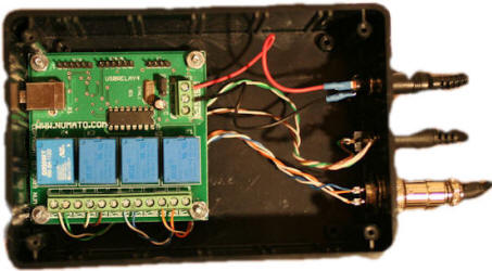
| The
USB
Relay Module is mounted within the box so that the USB
connector is flush against the inside wall of the box. The
remaining wires are connected as shown in the schematic on
the right. Refer to the
USB
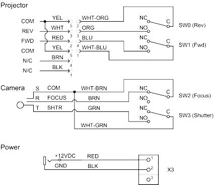
Relay Module Manual for more information. The connections shown on the right-hand edge of this schematic are on the relay module itself. The connections shown on the left-hand side of the schematic connect to external devices (projector, camera, and 12V DC 100mA power supply). {The schematic for the Camera socket to the USB Relay Module was edited 12-22-2011.} The color codes shown on the right side of the schematic are for the wire selected to use inside the box (conductors from a Cat-5 cable). The wiring colors internal to the box are not important. However, The colors shown on the projector cable are very important and you can use these colors to ensure you have connected the correct remote control lines to the relay module ports (SW0 through SW3). |
 |
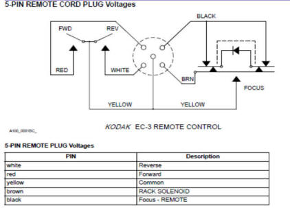 |
For reference, the detailed connections for the carousel remote control jack are shown here. |
|
This cable and connector is a standard 2.5 mm cable that is used for cell phone and cordless headsets. Before You Connect the Box to Your ComputerOnce your box is built, wait until the ClickSlide software (see below) is installed before connecting the box to your computer with a USB printer cable. You will need a driver that this software provides to make sure the box works properly. |
 |
 ClickSlide Software Installation
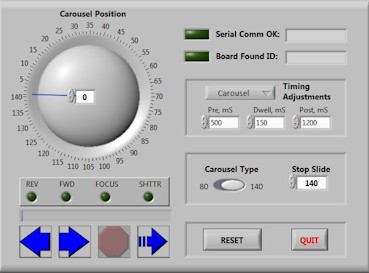
The ClickSlide software is used to coordinate the carousel and camera operation during conversion. This software is available as a free download (Approx. 100 MB). This is a very large download and will work best with a high-speed internet connection.
To download and install the ClickSlide software, click this link and choose "Run", or choose "Save As…" and then run the self-extracting executable after it has downloaded. Choose all of the default installation options and the software will install to your computer.
The first time you connect your control box to your computer, it will prompt you for a driver. This driver will be located on your desktop in a folder called "ClickSlide Driver". Use the Device Manager in Windows (or choose "Have Disk...") during the device driver installation process to point to this folder.
Once the driver is installed, you can delete this desktop item containing the driver.
 ClickSlide
Software Operation
ClickSlide
Software Operation
The Software for the ClickSlide Box will run on anything with Windows XP or later, 32 or 64 bit. 1 GB of RAM for Vista or Later (0.5 MB for WinXP). The computer must have a USB port.
Here is my computer setup:
- Intel(R) Core(TM)2 Duo CPU E6850 @ 3.00GHZ 2.99 GHz
- Memory (RAM): 4.00 GB
- System type: 32-bit Operating System
- Display Adapter: ATI Radeon HD 3800 Series
Additional Computer Software (Optional)
- Use Windows Live Photo Gallery (free from Microsoft) for light editing, dating and "tagging" photos.
- Use 1-4aRename for batch renaming files. (freeware)
- I use Corel PaintShop Photo Pro X3 for advanced editing such as batch converting Mirror Images and editing RAW files.
For more information see Operating
the Slide Converter page.